Methods / Power Factor Correction
How RokBench checks this
Power Factor Correction
Sizing shunt capacitors for a target power factor, and the cautions that come with them.
1. What this check does
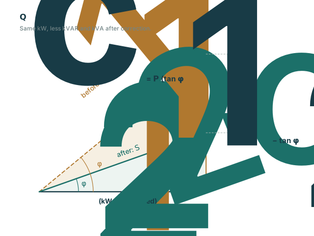
Computes the reactive power a shunt capacitor bank must supply to raise a load from its present power factor to a target, and the resulting apparent power and line current.
2. Inputs used
- Real power (kW), present and target power factor.
- Optional: system voltage and phases, for currents.
3. Formulas and assumptions
Capacitor kVAR
Apparent power
Current
Three-phase, kVA and V line-to-line.
Symbols
| Real power, unchanged by correction | kW | |
| Power factor angle before and after correction | ° | |
| Capacitor rating | kVAR | |
| Apparent power | kVA | |
| Line-to-line voltage | V | |
| Line current | A |
- Real power is unchanged by the correction.
- Capacitor kVAR is at rated voltage; actual output varies with the square of the applied voltage.
- A warning is raised when a fixed bank sized for full load would leave little margin before the power factor turns leading.
4. What is NOT checked
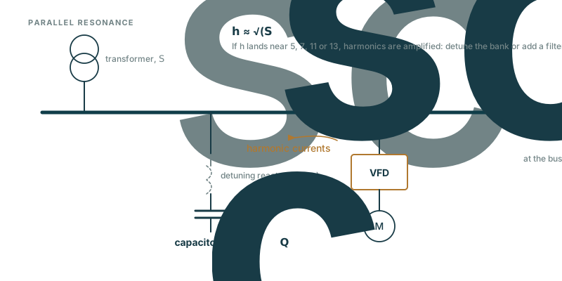
- Harmonic resonance and detuning.
- Switching transients and capacitor inrush.
- Utility tariff rules for power factor.
5. Reference standards
Pointers only; consult the edition adopted by your authority having jurisdiction.
- IEEE Std 18 — shunt power capacitors
- IEEE Std 1036 — application of shunt capacitors
- IEEE Std 519 — harmonic control
6. Validation cases
No worked example with a published answer is registered for this page yet. Have one we should add? Use the Feedback link. All cases: Validation.
7. Known issues and changes
See the Engineering Notes. Try the tool: PF Correction.