Cable Check
What the check does, the formulas behind it, and what it deliberately leaves out.
1. What this check does
For a cable you have already chosen, RokBench computes the load current, compares the design current per set with the cable's allowable ampacity, and estimates the running and motor-starting voltage drop along the cable. It reports what does not hold up and why. It does not select a cable, although it may point to the smallest size in the same cable family that would pass.
2. Inputs used
- Load as amperes, kW, HP or kVA; system voltage; single- or three-phase; power factor; efficiency (kW, HP).
- Load class: motor, continuous or non-continuous.
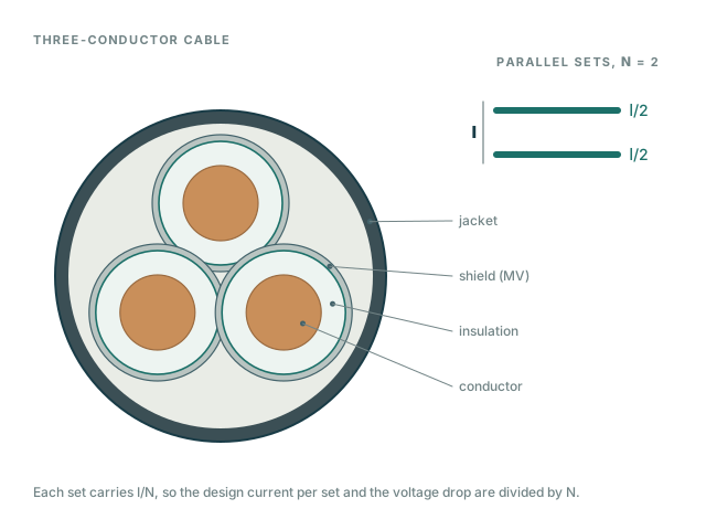
- Cable family and size, number of parallel sets, length, installation method and ampacity temperature column.
- Design ambient temperature (prefilled, editable) and an optional grouping adjustment factor — or a combined correction factor that replaces both.
- Optional: system frequency, motor starting method, starting current multiple and starting power factor, voltage drop limits.
3. Formulas and assumptions
Load current
V line-to-line. η applies to kW and HP inputs.
Blank efficiency uses the DOE minimum for the rating (10 CFR 431.25).
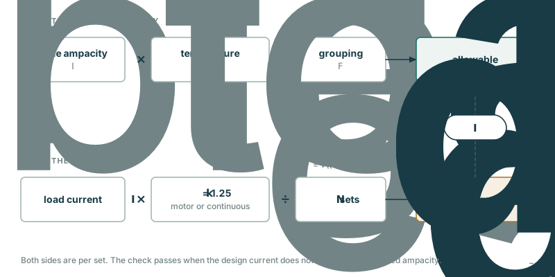
Design current and ampacity
k = 1.25 for motor and continuous loads, 1.0 otherwise; N = parallel sets.
NEC 430.22: 125 % of motor current against the corrected ampacity.
NEC 210.19(A)(1), 215.2(A)(1): 125 % before correction at the termination column (110.14(C)), 100 % after correction.
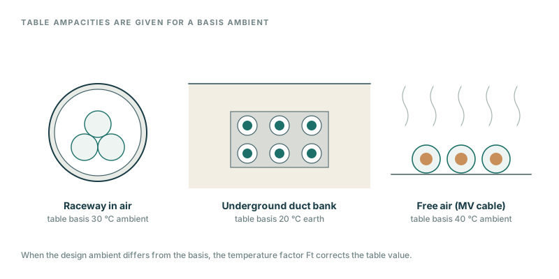
NEC 310.15(B)(1). Tc conductor rating, Ta′ design ambient, Ta basis ambient; Fg grouping adjustment.
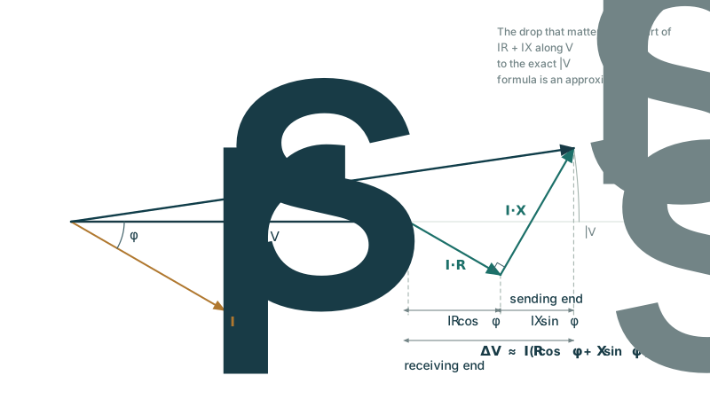
Voltage drop
c = √3 three-phase, 2 single-phase; R, X in Ω per 1000 ft per conductor; L in ft.
Starting drop: same formula with the starting current and starting power factor.
Symbols
| Real power of the load (kW, or HP converted) | kW | |
| Apparent power | kVA | |
| System voltage, line-to-line for three-phase | V | |
| Power factor and its angle, PF = cos φ | ||
| Motor or equipment efficiency | ||
| Load current | A | |
| Continuous or motor load multiplier (1.25 or 1.0) | ||
| Number of parallel sets | ||
| Table ampacity, allowable ampacity after correction | A | |
| Temperature correction factor, grouping adjustment factor | ||
| Conductor rating, table basis ambient, design ambient | °C | |
| √3 for three-phase, 2 for single-phase | ||
| One-way circuit length | ft | |
| Conductor resistance and reactance | Ω per 1000 ft |
- R, X and ampacity come from the cable library, which is built from manufacturer data sheets. The source is cited with every result. Rows still under source review are flagged.
- R is the AC resistance at the temperature stated in the data (typically the conductor rating). No further temperature adjustment is made, which is conservative for lightly loaded cables.
- X is scaled in proportion to frequency when the system frequency differs from the data.
- HP with efficiency left blank uses the US federal minimum for a 4-pole enclosed motor of that rating (10 CFR 431.25, 2016 levels); the result says so.
- The voltage drop formula is the common approximate form, accurate for the small angle between sending and receiving voltages found in feeder and branch circuits.
- The ampacity is corrected for ambient temperature by the NEC equation. The design ambient defaults to 40 °C for raceway and free air and 20 °C (earth) for underground duct — RokBench assumptions you should replace with the site value. “Fill from coordinates” takes the site value from NASA POWER climatology (2001–2020): by default the highest temperature recorded in that period, with the hottest month's average daily high offered as an alternative; both are grid averages and can read low for cities. The basis ambient of the rating is taken as 30 °C for raceway (NEC 310.16), 40 °C for free air and 20 °C for underground duct (NEC 311.60). The rooftop adder of NEC 310.15(B)(2) (33 °C for raceways less than 7/8 in above a roof) is not applied automatically — add it to the ambient you enter.
- Two ampacity conditions, as the NEC writes them. Motor circuits: 125 % of the motor current must not exceed the corrected ampacity (430.22). Feeders and branch circuits: 125 % of the continuous load (plus the non-continuous load) must not exceed the table value before correction — for low-voltage raceway the 75 °C column, the usual termination rating (110.14(C)) — and the full load must not exceed the corrected ampacity.
- Grouping (more than three current-carrying conductors) is not applied unless you enter an adjustment factor. A combined correction factor, if entered, is used as-is instead of the temperature and grouping factors.
- If you do not set voltage drop limits, a default limit is applied and shown with the result. Set the limits your project criteria require.
4. What is NOT checked
- Upstream voltage drop and source impedance. Starting drop is the cable drop only, not the voltage at the motor terminals.
- Harmonics, phase imbalance, neutral current and cable heating from non-sinusoidal loads.
- Short-circuit withstand, overcurrent protection and coordination.
- Termination temperature limits beyond an informational note.
- Conduit fill, tray fill, pulling tension and bending radius.
5. Reference standards
Pointers only; consult the edition adopted by your authority having jurisdiction.
- NEC 2023 430.6(A)(1), 430.22 — motor full-load current and conductor sizing
- NEC 2023 215.2(A)(1), 310.14, 310.15 — feeder sizing, ampacity and correction
- NEC 2023 310.10(G) — conductors in parallel
- NEC 2023 110.14(C) — termination temperature
- NEC 2023 210.19(A) Informational Note No. 4, 215.2(A)(2) Informational Note No. 2 — voltage drop recommendations
6. Validation cases
Hand-calculated cases run on every change. Published textbook cases will be listed on the Validation page.
7. Known issues and changes
See the Engineering Notes. Try the tool: Cable Check.