Short-Circuit Duty: ANSI vs IEC
Two standard families answer the same question — can this breaker handle the fault? — with different currents and different ratings.
1. What this check does
Builds the impedance of one radial path (utility source, transformer, cable) and any motor contribution at the fault bus, then calculates a bolted three-phase fault two ways. ANSI/IEEE C37: symmetrical current at 1.0 pu prefault voltage, its X/R from separate R and X networks, and a multiplying factor when the system X/R is above the breaker's test X/R; the adjusted duty is compared with the symmetrical interrupting rating, and the first-cycle peak with the close-and-latch rating. IEC 60909: initial symmetrical current Ik″ with the voltage factor c and the transformer correction KT, peak ip, breaking current Ib, DC component and thermal equivalent Ith; compared with Icu or Isc, Icm and Icw.
2. Inputs used
- Fault bus voltage and frequency; utility short-circuit MVA and X/R, or an infinite bus.
- Optional transformer (kVA, %Z, X/R), cable (length, R and X per conductor, parallel sets) and running motors (kVA, Xd″, X/R, ANSI multipliers).
- Breaker type and test X/R (prefilled with typical values), contact parting time for MV breakers, and the ratings of each standard family that you want checked.
- IEC minimum break time tmin and fault duration Tk; LV voltage tolerance for cmax.
3. Formulas and assumptions
Impedances on the fault-bus voltage
Cable: R and X per conductor × length ÷ parallel sets. Motors: Z_M = Xd″ on the motor kVA.
ANSI / IEEE C37
1.0 pu prefault voltage; motor impedance × the first-cycle or interrupting multiplier.
(X/R)t = breaker test circuit X/R. MF is not taken below 1.
Remote source, t = contact parting time in cycles, (X/R)t = 17 at 60 Hz.
IEC 60909
c = 1.05 (LV, ±6 %) or 1.10 (LV ±10 %, and MV); xT = transformer reactance in per unit.
Summed over the network branch and the motor branch.
Far from generators; full motor contribution kept.
Symbols
| Fault-bus line-to-line voltage; frequency | V, Hz | |
| Utility short-circuit power; transformer rating and impedance | MVA, kVA, % | |
| Impedance at the fault and its parts | Ω | |
| ANSI symmetrical, first-cycle asymmetrical rms and peak current | kA | |
| Breaker test circuit X/R (from its test power factor) | ||
| ANSI multiplying factor; MV contact parting time | —, cycles | |
| IEC voltage factor; transformer correction; transformer reactance | per unit | |
| IEC initial symmetrical, peak and breaking current | kA | |
| Peak factor from R/X | ||
| DC component at the minimum break time | kA, s | |
| Thermal equivalent current over the fault duration; DC and AC heat factors | kA, s, — | |
| IEC breaking (LV, MV), making, short-time withstand ratings and its duration | kA, s |
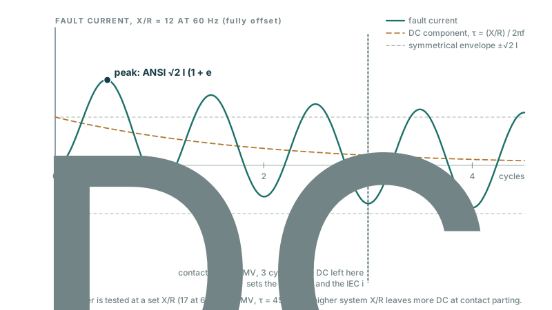
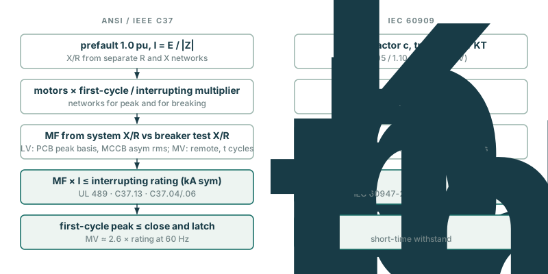
- One radial path and a bolted three-phase fault. Nearby generators are not modelled, so ANSI uses the remote-source multiplying factor and IEC treats the fault as far from generators (Ib = Ik″).
- ANSI magnitudes use the complex impedance (E/Z); X/R comes from separately reduced R and X networks as ANSI practice requires.
- Motor contribution: ANSI multiplies the motor impedance by the first-cycle and interrupting multipliers you enter (0 removes motors from the interrupting network). IEC keeps the full motor contribution in Ib (no μ·q decay), which is conservative.
- Breaker test X/R values and ANSI motor multipliers are prefilled with commonly used figures for convenience; RokBench does not reproduce the standards’ tables — confirm them for the edition you apply.
- MV close-and-latch and IEC making ratings default to 2.6 × (60 Hz) or 2.5 × (50 Hz) the interrupting rating when not entered.
- Cable resistance is used as entered; for maximum fault current use the resistance at 20 °C.
4. What is NOT checked
- Unbalanced faults (line-to-ground, line-to-line) and arcing faults or arc flash.
- Generator-dominated (local) contributions, decrement of synchronous machines, and meshed networks.
- Series ratings, current-limiting fuses and let-through, and coordination.
- Bus bracing and cable withstand (use Ith and the conductor data).
5. Reference standards
Pointers only; consult the edition adopted by your authority having jurisdiction.
- IEEE Std C37.010 — application guide for AC high-voltage circuit breakers (symmetrical current basis)
- IEEE Std C37.04 / C37.06 — MV breaker ratings; IEEE Std C37.13 — LV power circuit breakers; UL 489 — molded-case breakers
- IEEE Std 551 (Violet Book) — short-circuit calculations
- IEC 60909-0 — short-circuit currents in three-phase AC systems
- IEC 62271-100 — HV/MV circuit breakers; IEC 60947-2 — LV circuit breakers (Icu, Ics, Icm, Icw)
6. Validation cases
These worked examples run through the engine on every change; the expected values come from the cited source. All cases: Validation.
480 V bus behind 1500 kVA, 5.75 % Z, X/R 6 — ANSI and IEC shortcircuit/duty · Hand calculation
PassSource: Hand calculation from the ANSI (IEEE C37.13 practice) and IEC 60909-0 equations on the Methods page — Zt = 0.0575 · 480² / 1.5 MVA = 8.832 mΩ. ANSI: I = 480/(√3·Zt) = 31.38 kA; asym = I·√(1+2e^(−2π/6)) = 40.93 kA; peak = √2·I·(1+e^(−π/6)) = 70.66 kA; MCCB MF = 1.3046/1.2469 = 1.046. IEC: c = 1.05; xT = 0.0567; KT = 0.95·1.05/(1+0.6·0.0567) = 0.9647; Ik″ = 1.05·480/(√3·KT·Zt) = 34.15 kA; κ = 1.02+0.98e^(−0.5) = 1.614; ip = κ·√2·Ik″ = 77.98 kA.
| Quantity | Expected | RokBench | Error | Result |
|---|---|---|---|---|
| ansi.firstCycleKa | 31.38 | 31.38 | 0% | Pass |
| ansi.asymRmsKa | 40.93 | 40.93 | 0% | Pass |
| ansi.peakKa | 70.66 | 70.66 | 0% | Pass |
| ansi.multiplyingFactor | 1.046 | 1.046 | 0% | Pass |
| iec.kt | 0.9647 | 0.9647 | 0% | Pass |
| iec.ikssKa | 34.15 | 34.15 | 0% | Pass |
| iec.kappa | 1.614 | 1.614 | 0% | Pass |
| iec.ipKa | 77.98 | 77.98 | 0% | Pass |
7. Known issues and changes
See the Changelog. Try the tool: Short-Circuit Duty: ANSI vs IEC.